Testing scikit-rf and Emerge, open source RF stuff
I wanted to test some open source RF tools and made a small project with them. The idea is to simulate a mock matching circuit for an amplifier and test EMerge for some stub simulations. This is not a simulation of a real system. I chose an LNA for simulations as their input matching is usually slightly bad and can be improved. Note that real LNAs have ‘bad’ input matching to minimize noise; this is not a practical simulation and just to try out tools.
Matching amp with lumped elements in scikit-rf
I chose a Mini-circuits PSA4-5043+ as an amplifier. As an LNA, it showed an input match that can be improved. I wanted to try scikit-rf to create an initial matching test.
I downloaded the public S-parameters of the LNA and started tuning them with an input matching network in scikit. To have little more complexity I wanted to try a double L-section match thinking this would result in double stub tuning when doing a distributed layout.
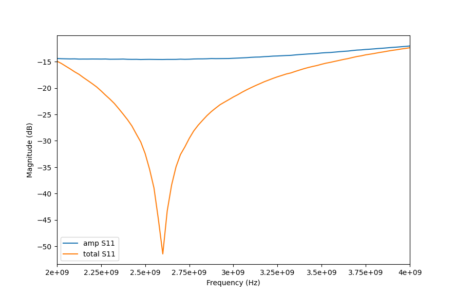
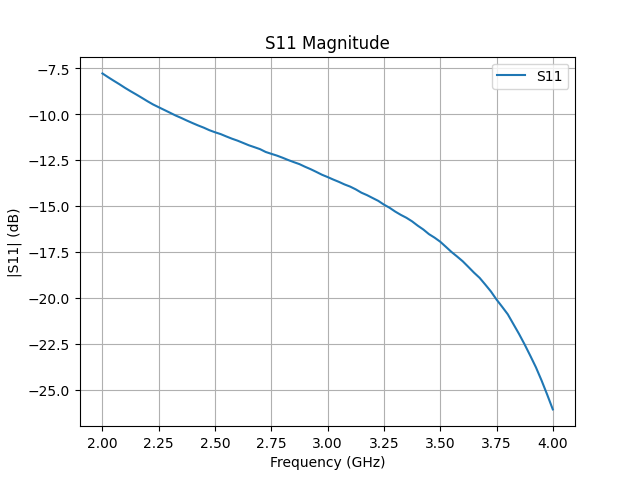
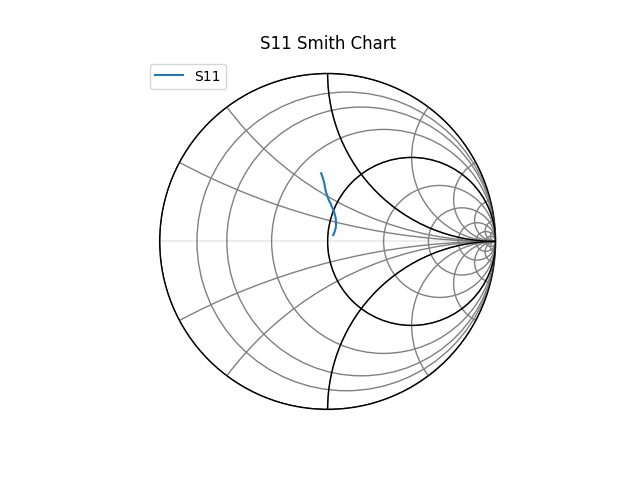
Below are the compared S11 of the amplifier and the amplifier and the input system.
| Magnitude | Smith |
|---|---|
 |
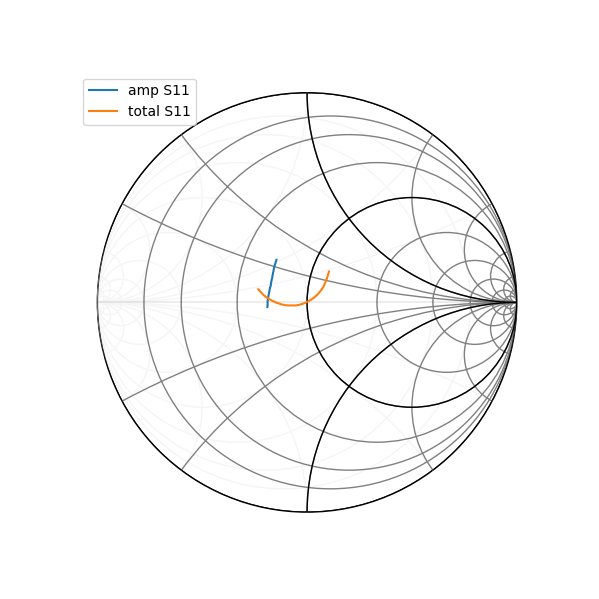 |

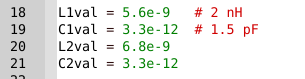
Testing was mainly done with smith chart tuning manually. These were the lumped values I decided to use in the end. I wanted them to match common lumped values. Although this is a bit redundant as I will make a distributed network.
Trying to create distributed stubs
I could use richard transforms and kuroda transforms. I planned this badly and realised that series capacitors are difficult to deal with. I chose to simply turn the inductors into shorted stubs; the capacitors will be left as lumped components. This way I can test some multiport simulations.
The stackup is of the following:
Ro4350b
18um Co
0.508mm
18um Co
min via hole size 0.2mm
EMerge is used to create and simulate the 3d geometry. The lumped slots are left as terminal ports. This technique is also showed in one forum article.
Issues here. I discarded a possible bias as I wanted a simple simulation. A bias tee can change the behaviour. The model generally is also extremely simple.
The inductive shorts will be around 0.28mm wide. This may not be within specs realistically. For lengths L1 = 8.4mm, L2 = 9.5mm. Otherwise traces are 50ohm on the traces.
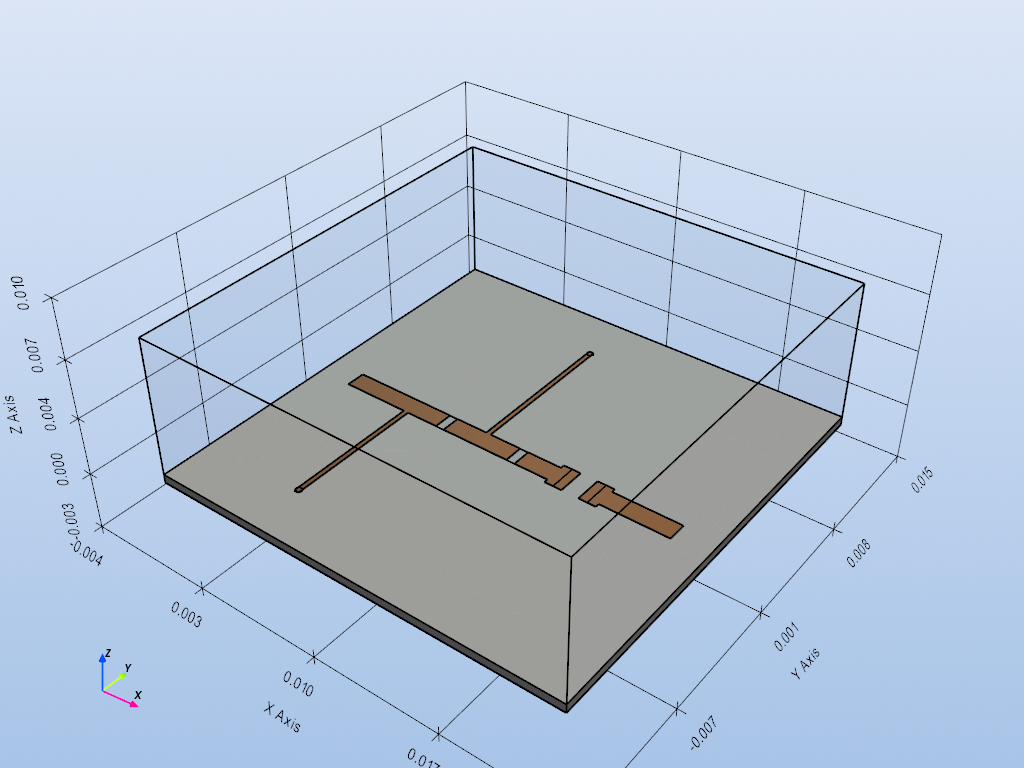
The model shows holes for the capacitors and ports for the amplifier S-parameters. This simulation gives a s6p file where the caps and amplifier s paramters will be inserted. I used lumped ports for total inputs. Modals can also be used easily although my system is capped on resources.
Results for stub system
The match will naturally move with the EM compared to the ideal lumped model. I insert ideal capacitors into the capacitor ports and insert the chosen amplifier to the amplifier inputs and outputs. This is done with scikit-rf
| Magnitude | Smith |
|---|---|
 |
 |
It can be seen that the match still is improved compared to the unmatched amplifier. It is clear that the match point has moved up in frequency. It is adviseable to tune the stubs to see their effects.
EMerge is effective for simple quick simulations. I could make a better workflow as these simulaitons were done in a fractional manner. Although the idea was to test the open source stuff and they do clearly work
This workflow can substitute commercial microwave circuit software in a pinch. Although again the lack of a schematic GUI makes the work slow. Scikit-RF syntax is not difficult and can be learned and vibe coded pretty effectively.